English
 Русский язык
 بالعربية


Products Description
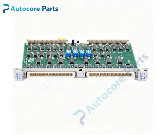
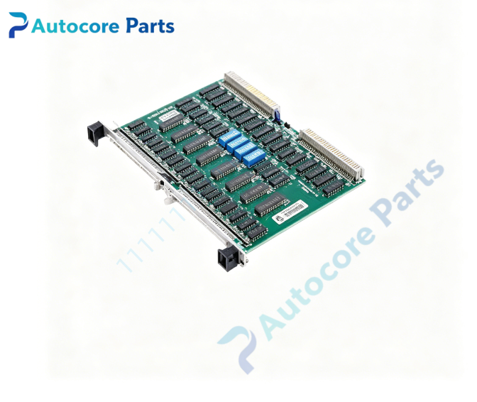
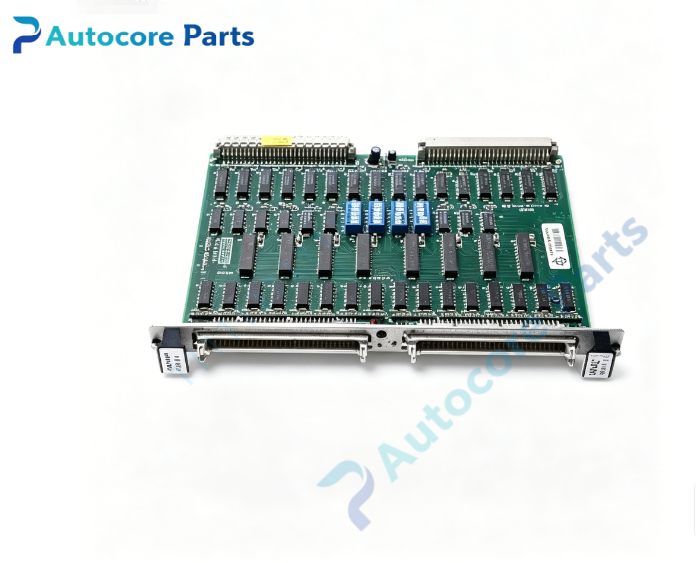
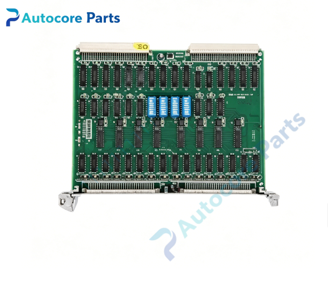
VMIC VMIVME-2120 Digital Output Board
Module Feature
VMIVME-2120 is a double-slot 6U VMEbus high-voltage digital sink output board developed by VMIC (GE Fanuc / Abaco Systems). It supplies 64 independent open-collector output channels for driving relays, contactors and solenoid inductive loads. Each channel supports 5–48 VDC load voltage,single channel sink current up to 600 mA,breakdown voltage 55 V; multiple channels can be paralleled to achieve higher drive current. Onboard flyback suppressor diodes absorb reverse EMF from inductive loads,optional overcurrent shutdown protection cuts off output when exceeding 1 A per channel. VME bus interface supports A16 addressing and D08/D16/D32 data transfer,operates exclusively as VME slave. Separate address switches configure control status register and data register,consecutive address mapping available when stacking multiple boards. Built-in BIT logic enables software-controlled channel status readback and fault detection;front panel FAIL LED indicates module diagnostic failure. Rugged Eurocard PCB with conformal coating,shock and vibration screened for power plant cabinet environment,widely used in gas/steam turbine sequence control,aerospace ground test bench and industrial VME control chassis.
Working principle
VME host writes digital logic states to 8 × 8-bit output registers. Register signals control open-collector sink transistors to pull down field load circuits. Flyback diodes clamp high reverse voltage generated by inductive loads during switch-off. BIT circuit writes preset test patterns and reads back actual channel states to verify hardware integrity. VME FPGA performs address decoding and bidirectional data handshake between VME backplane and register bank. Overcurrent protection circuit triggers shutdown to protect driver transistors when overload occurs.
Onboard components
VME interface FPGA,8 × 8-bit output register array,64 channel open-collector driver network,inductive flyback clamp diode array,BIT status readback logic,overcurrent protection circuit,dual address switch banks,VME J1/J2 edge connector,front-panel P3/P4 64-pin DIN I/O connectors,multi-status LED array.
LED indicators
Front panel LED indicators for module FAIL fault alarm.
Hardware self-diagnosis
Visual inspection of PCB,components and solder joints;board ID register readback verification;BIT channel pattern write-readback test;overcurrent protection trigger test;VME A16 read/write communication test.
Programming software
VMIC intelligent I/O driver library and configuration utility,supports VxWorks,Linux and QNX real-time operating systems;software tool for output bit setting and fault log retrieval.
Electrical & Process Parameters
Model: VMIVME-2120 Brand: VMIC Device type: Double-slot 6U VMEbus 64 channel high voltage digital sink output module Bus standard: VMEbus, A16 addressing, D08/D16/D32 transfer Channel count:64 Output type: Open collector sink Load voltage:5–48 VDC,max breakdown 55 V Per channel sink current:600 mA typical Control mode: VME slave access,multi-board contiguous address mapping,BIT built-in self-test,inductive flyback clamping,optional 1 A overcurrent shutdown Power supply: +5 V from VME backplane Cooling: Convection cooling Protection: Inductive flyback clamping,overcurrent cutoff,ESD protection Mounting: Double-height 6U VME front panel ejector locking Protection class: PCB with optional conformal coating
Mechanical & Structure
Mounting: Double-slot 6U VME Eurocard Protection class: PCB with optional conformal coating
Environmental
Operating temperature:0℃ ~ +55℃ Storage temperature:-40℃ ~ +85℃ Ambient humidity:20~80% non-condensing Certification: CE compliant Status: VMIC double slot 6U VME high voltage digital output board
Installation
Follow ESD safety procedure before handling.Fully power off VME chassis.Insert VMIVME-2120 into vacant double-height 6U VME slot and lock front panel ejector latches.Set address switches for CSR and data registers.Wire field relays and solenoid loads to front P3/P4 DIN connectors.Power on chassis,load VMIC I/O driver,run BIT channel diagnostic before commissioning.
Interface
VME J1/J2 backplane connector,front-panel dual 64-pin DIN field I/O connector,fault status register pins.
Diagnostic
Board undetected: poor VME backplane contact,damaged edge connector or incorrect address switch setting. Individual channel no output: open field wiring or burnt output transistor. Front FAIL LED lit: BIT pattern mismatch or overcurrent shutdown triggered. Channel damage after repeated switching: missing flyback clamp protection.
Product Brief
VMIC VMIVME-2120 double height 6U VME high voltage digital output board,64 channel open-collector sink output with 600mA per channel,built-in BIT and inductive load protection,for turbine sequence control and test bench VME systems.