English
 Русский язык
 بالعربية


Products Description
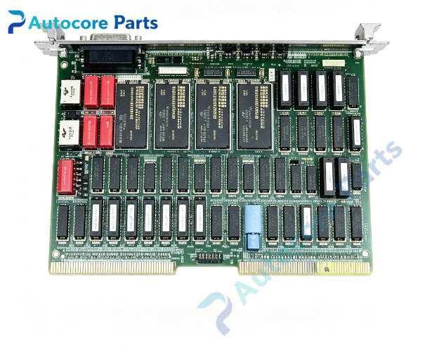
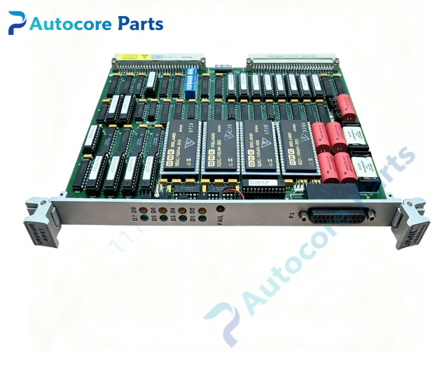
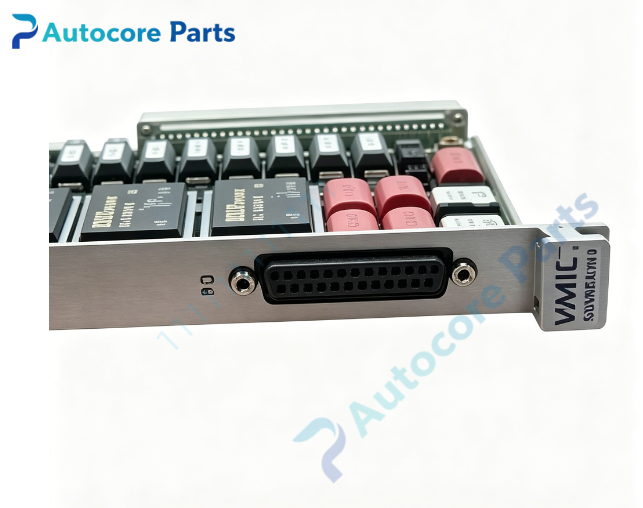
VMIC VMIVME-4941 Quad Synchro / Resolver To Digital Converter Board
Module FeatureVMIC VMIVME-4941 is a double-slot 6U VMEbus synchro/resolver-to-digital converter board with four independent measurement channels, used to convert analog synchro or resolver rotary position signals into digital position values. Resolution can be programmed via software: 10 bit,12 bit,14 bit,16 bit, balancing tracking speed and measurement precision. Bandwidth has two software options: 130 Hz for high precision and 530 Hz for high dynamic response. Max resolver tracking speed reaches 800 rps (48000 rpm), synchro tracking rate up to 160 rps. Each channel integrates a 16-bit pitch counter for multi-turn position recording. Reference input frequency ranges from 360 Hz to 6 kHz, reference voltage 4~50 Vrms; signal input supports 2 V,11.8 V or 90 V line-line jumper selection. Accuracy optional up to ±2.3 arc minutes. Supports 8/16/32 bit VME data transfer modes. Onboard Built-In-Test (BIT) function can verify converter hardware integrity, with signal loss and over-error status reporting. Rugged double Eurocard construction, widely used for CNC spindle position, robot axis, radar antenna, turbine rotary feedback and high precision motion control VME chassis.
Working principleAnalog synchro/resolver differential excitation signals from rotary transducers are fed into P2 rear connector. The R/D or S/D hybrid chip continuously tracks angular position and converts analog phase difference into digital position code. Onboard register stores position data and pitch count for VME master reading. Software configures resolution and bandwidth to adapt slow high-precision or fast dynamic rotation. BIT diagnostic circuit performs internal loopback test and monitors signal loss and position error exceeding threshold. VME interface handles address decoding and data handshake for host access to position and fault status registers.
Onboard componentsQuad synchro/resolver to digital converter hybrid modules,16-bit pitch counter per channel,reference signal conditioning circuit,software bandwidth filter, VME address decode FPGA, BIT diagnostic logic, front panel status LED array, configuration jumpers, P2 rear field signal connector.
LED indicatorsFront panel LED indicators for board power, signal present, error over threshold and board fail alarm. Fail LED lights on power reset and can be cleared by software after successful BIT test.
Hardware self-diagnosisVisual inspection of PCB, front ejectors and solder joints; board ID register readback and firmware verification; BIT internal loopback test for all four channels; resolution and bandwidth switching test; tracking rate validation; VME 8/16/32 bit read/write communication test.
Programming softwareVMIC VME device driver library, position acquisition and BIT diagnostic utility, compatible with VxWorks, Linux and Windows embedded real-time operating systems.
Electrical & Process ParametersModel: VMIVME-4941 Device type: Double-slot 6U VMEbus synchro/resolver-to-digital converter Bus standard: VMEbus Channel count: 4 independent R/D / S/D channels Resolution: Software selectable 10 /12 /14 /16 bit Tracking rate: Max 800 rps for resolver,160 rps for synchro Bandwidth: 130 Hz / 530 Hz software selectable Reference input: 4~50 Vrms, 360 Hz ~ 6 kHz Control mode: VME slave access, BIT built-in self-test, pitch counter recording Power supply: +5 V, ±15 V from VME backplane Cooling: Convection cooling Protection: Loss-of-signal detection, over error alarm, ESD protection Mounting: Double-height 6U VME front panel ejector locking Protection class: PCB with optional conformal coating
Mechanical & StructureMounting: Double-slot 6U VME Eurocard Protection class: PCB with optional conformal coating
EnvironmentalOperating temperature: 0℃ ~ +60℃ Storage temperature: -40℃ ~ +85℃ Ambient humidity: 5~95% non-condensing Certification: CE compliant Status: VMIC four channel VME resolver/synchro position digitizer board
InstallationFollow ESD safety procedure before handling. Fully power off VME chassis. Insert VMIVME-4941 into vacant double-height 6U VME slot and lock front panel ejector latches. Set onboard jumpers for signal input voltage and differential/direct input mode. Wire resolver or synchro rotary transducers to rear P2 connector. Power on chassis, load VMIC driver, configure resolution and bandwidth, execute BIT self-test before commissioning.
InterfaceVME J1/J2 backplane connector, P2 rear synchro/resolver analog signal terminal, fault status signal pins.
DiagnosticBoard undetected: poor VME backplane contact, damaged edge connector, incorrect address jumper setting. Position reading jumping: reference signal amplitude out of range, loose transducer wiring, wrong bandwidth setting. BIT test failure: R/D hybrid module fault or reference conditioning circuit damage. Signal loss alarm: broken field cable or resolver transducer failure.
Product BriefVMIVME-4941 VMIC double height 6U VME quad synchro/resolver to digital converter board,software programmable resolution and bandwidth,with BIT self-test,for high precision rotary position feedback,radar antenna and motion control VME systems.